The next PDF document contains DIY retrofit instructions, for replacing the standard BMW E46 pre facelift dome lights with the newer ones with map light function.
The document is in Romanian, but the schematic is pretty clear... anyway if you need any help just contact me.
You can find the DIY document in the next link:
https://drive.google.com/file/d/0BxkwKKtkK3eRTkQxai1Pa0JGVkU/view?usp=sharing
Friday, 22 January 2016
Monday, 11 January 2016
Droidbot #3 - Controlling the robot direction via a light source
The direction of the robot will be given by a light source. It will try to follow the light source.
To achieve this there are two photo resistors on each side of the robot.
Both of them are connected in a Wheatstone bridge and the output of the bridge is connected to an operational amplifier.
 On the software side, we have to initialise the GPIO input pins and configure the interrupts on these pins.
A few words on interrupts:
The function to initialise the GPIO pins is: GPIO_Light_sensor_init(), see file on Git Hub here.
The priority of this interrupt is configured to be 2 (0 being the highest and 7 being the lowest priority).
The function for the ISR is: GPIO_PortF_Handler(), see file on Git Hub here.
The name of this function must be predefined in the start up code, see file on Git Hub here.
It is recommended that as early as possible in the ISR to acknowledge the interrupt so that it will not self trigger again.
This was done with the GPIOIntClear API.
Also it's recommended not to have delays in the ISR, since we could loose the real time characteristic of our system.
Again, if something is not clear, feel free to comment. I will add more details to the article.
To achieve this there are two photo resistors on each side of the robot.
Both of them are connected in a Wheatstone bridge and the output of the bridge is connected to an operational amplifier.

A few words on interrupts:
- Interrupts are signals to the processor, to stop the execution of the current code / context and execute some different code in a different context.
- They can be generated by various devices, events, processes
- Ex. rising / falling edge on a digital input pin, timer reset, analog input reaches a certain value, etc.
- The part of the SW that defines what actions are to be taken when the interrupt occurs, is called ISR (Interrupt Service Routine).
- For more details on interrupts check the next articles ( polling vs interrupts, wikipedia)
The function to initialise the GPIO pins is: GPIO_Light_sensor_init(), see file on Git Hub here.
The priority of this interrupt is configured to be 2 (0 being the highest and 7 being the lowest priority).
The function for the ISR is: GPIO_PortF_Handler(), see file on Git Hub here.
The name of this function must be predefined in the start up code, see file on Git Hub here.
It is recommended that as early as possible in the ISR to acknowledge the interrupt so that it will not self trigger again.
This was done with the GPIOIntClear API.
Also it's recommended not to have delays in the ISR, since we could loose the real time characteristic of our system.
Again, if something is not clear, feel free to comment. I will add more details to the article.
Wednesday, 6 January 2016
Droidbot #2 - DC Motor control
In this article I will describe the software & hardware driver for the DC motors.
Instead of configuring directly the uController registers, I've chosen to use the Texas Instruments API's from the TivaWare librare... a far more efficient and reliable methot.
So, the two motors are separately powered from the battery and the uController provides only the "On/Off" signal for them.
On the hardware side, I chosen to use a dual motor driver from Pololu (more details in here).
On the left side, you have the interface with the uController and on the right side, with the battery and DC motors.
Lets name the two motors A and B.
To spin A in one direction, it's necessary to supply PWM signal to either AIN1 or AIN2. To spin it in the opposite direction, you need to supply PWM signal to the other AINx pin. The same is valid for motor B.
When one PWM signal is provided to spin in one direction, the other PWM signal should be disabled.
The rotation speed of the motors depend on the duty cycle of the PWM.
Instead of configuring directly the uController registers, I've chosen to use the Texas Instruments API's from the TivaWare librare... a far more efficient and reliable methot.
So, the two motors are separately powered from the battery and the uController provides only the "On/Off" signal for them.
On the hardware side, I chosen to use a dual motor driver from Pololu (more details in here).
On the left side, you have the interface with the uController and on the right side, with the battery and DC motors.
 |
| Motor driver interfaceAINx, BINx - PWM input from uC GND - Ground connection - common, VIN - (+) terminal from battery AOUTx, BOUTx - Analog outputs for the DC motors A and B |
To spin A in one direction, it's necessary to supply PWM signal to either AIN1 or AIN2. To spin it in the opposite direction, you need to supply PWM signal to the other AINx pin. The same is valid for motor B.
When one PWM signal is provided to spin in one direction, the other PWM signal should be disabled.
The rotation speed of the motors depend on the duty cycle of the PWM.
A few words about PWM:
- PWM is a method of generating "analog" signal with a digital output
- It's basically a square wave signal with a defined amplitude and frequency
- the RPM is controlled by the % of high signal (50% duty cycle means high signal duration = low signal duration)
Monday, 4 January 2016
Droidbot #1 - Concept & 1st prototype
Hello world,
In the next few articles I'm going to write about building a robot.
This will contain the SW code for controlling it, the electrical schematic and mechanical design.
The idea was to build a simple robot, with two wheels each powered by a DC gear motor.
This are controlled by a Texas Instrument development board (Tiva TM4C123G Launch Pad) that has a Cortex M4 MCU.
In the initial phase the direction of movement will be given by a light source for going forward & left or right and a sound source for going backward.
For forward motion, left or right direction a photo resistor (light sensor) will be used in a wheatstone bridge. Connected to an amplifier will drive the input pin of the uController.
For backward motion, a microphones output is RC filtered and connected to an amplifier. The analog output of it will be used in the uControllers analog comparator, so that when the analog input is larger than a defined value, the motors will spin backward.
A first prototype I already built for the ending project of an online course.
Which you can check out here.
For the software I used the Energia IDE, which is great if you're a hobbies and don't want to get in details with the SW development, which is NOT my case :)
So I decided to re-write the whole software in C, apply the techniques and knowledge I gained on my workplace, make the SW modular, re-usable, real time... some of the main requirements in a professional embedded system.
In the next video will show the functioning of this initial prototype.
In the next articles I will describe each functionality in part with SW code and electrical schematic.
Stay tuned :)
Friday, 22 August 2014
Action camera #3 - Basic software
In this section I'll introduce you to the software that will drive the camera.
I will not go into details, just show you it's layout and some basic functionality of the camera.
The software is writen in python and is structured in modules that represent the submenus of the device.
As you start up the camera, you'll have the following options and submenus (indented).
You can navigate through this with the Left & Right buttons, confirm selection with the Enter button and start recording with the capture button.
- Image capture
- Video recording
- Image settings
- Scene
- Resolution
- Shutter speed
- Aperture
- ISO
- White balance
- Saturation & sharpness
- Back
- Video settings
- Resolution
- FPS
- White balance
- Device settings
- Time & Date
- Exif
- Units
- Wifi
- GPS
- Sensors
- Power off
Action camera #2 - Hardware layout
The layout of the camera I intend to be as compact as possible, without exceeding a creditcard size (the size of the Raspberry Pi) and all in one enclosure.
However it is possible that during the project I will chose a two module design, having the "brain" + controls, batery and display in one module and the camera + sensors in a different module, conected by a cord.
In this post I'll describe the initial one enclosure layout, that I target to have.
In the front (bottom of the Raspberry Pi) we will have the camera module, the GPS module, the temperature and pressure sensor and a battery pack.

In the back (top of the Raspberry Pi) we will have a 16x2 monochrome LCD display and three buttons:
- Go left buttom: will make the "Selection Left" current
- Enter button: will confirm or execute "Current Selection"
- Go right button: will make the "Select Right" current
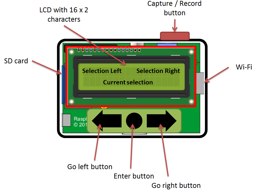
On the sides we'll have the SD card acces slot, the Capture / Record button and the Wi-Fi module.
Saturday, 9 August 2014
Action camera #1 - Concept & Intro
In the following post series I'll write about my new project, that is an action camera, powered by the Raspberry Pi mini computer. The final product should have similar features to the famous GoPro Hero action camera.
The brain of the gadget is a Raspberry Pi A, powered by a 700 Mhz processor with 256 MB of RAM. Should be powerful enough for 720p video and 5 MP image capture.
The "eye" will be the RaspiCam, a dedicated camera for the Raspberry Pi.
The controls will be from micro switches and it will use an 16x2 LCD for status display and configuration.
The software for the camera will be written in Python and will run on a simplified version of the Raspbian OS.
I don't have the full list of components required for this project at the moment, so in every stage I'll write the stuff that you'll need extra from the previous stage.
But for start:
- Raspberry Pi A or B
- 4GB or larger SD card
- RaspiCam
- Display with digital input (HDMI ori DVI-D)
- USB keyboard
- ~1A USB power supply.
Subscribe to:
Comments (Atom)